
“Think fast, act slow” […] is a hallmark of failed projects. Successful projects, by contrast, tend to follow the opposite pattern and advance quickly to the finish line.
Bent Flybjerg and Dan Gardner, How Big Things Get Done, p. XIII
Conversely, thinking slow and acting fast is the single most important practice to succeed with big and complex projects (see my newsletter #45 Think Slow, Act Fast for a summary of the book "How Big Things Get Done"). Think Slow, Act Fast was the reason why Frank Gehry could finish the Guggenheim Museum Bilbao ahead of time and under budget. Think Fast, Act Slow was the reason why the Sydney Opera House was ten years late and cost 14 times more than originally planned. The two stories illustrate another important point, which is true for building architecture as well as for embedded system architecture.
This raises a couple of questions.
- How can we identify the big architecture decisions? How can we identify the money pits?
- How can we mitigate the threat of falling into a money pit? How can we focus on our core business?
- How can we commoditise our non-core business? How can we reduce the costs of our product development?
Wardley maps help answer these questions. By drawing the Wardley map for a harvester, we can easily spot the crucial points of the architecture. We should discuss these points thoroughly, come to a decision and record the decision in an architecture decision record (ADR). If we learn something new about the point (feedback), we revisit our decision and adapt it if necessary. Getting the big decisions right early will save us a lot of trouble, time and money later.
Identifying the Money Pits
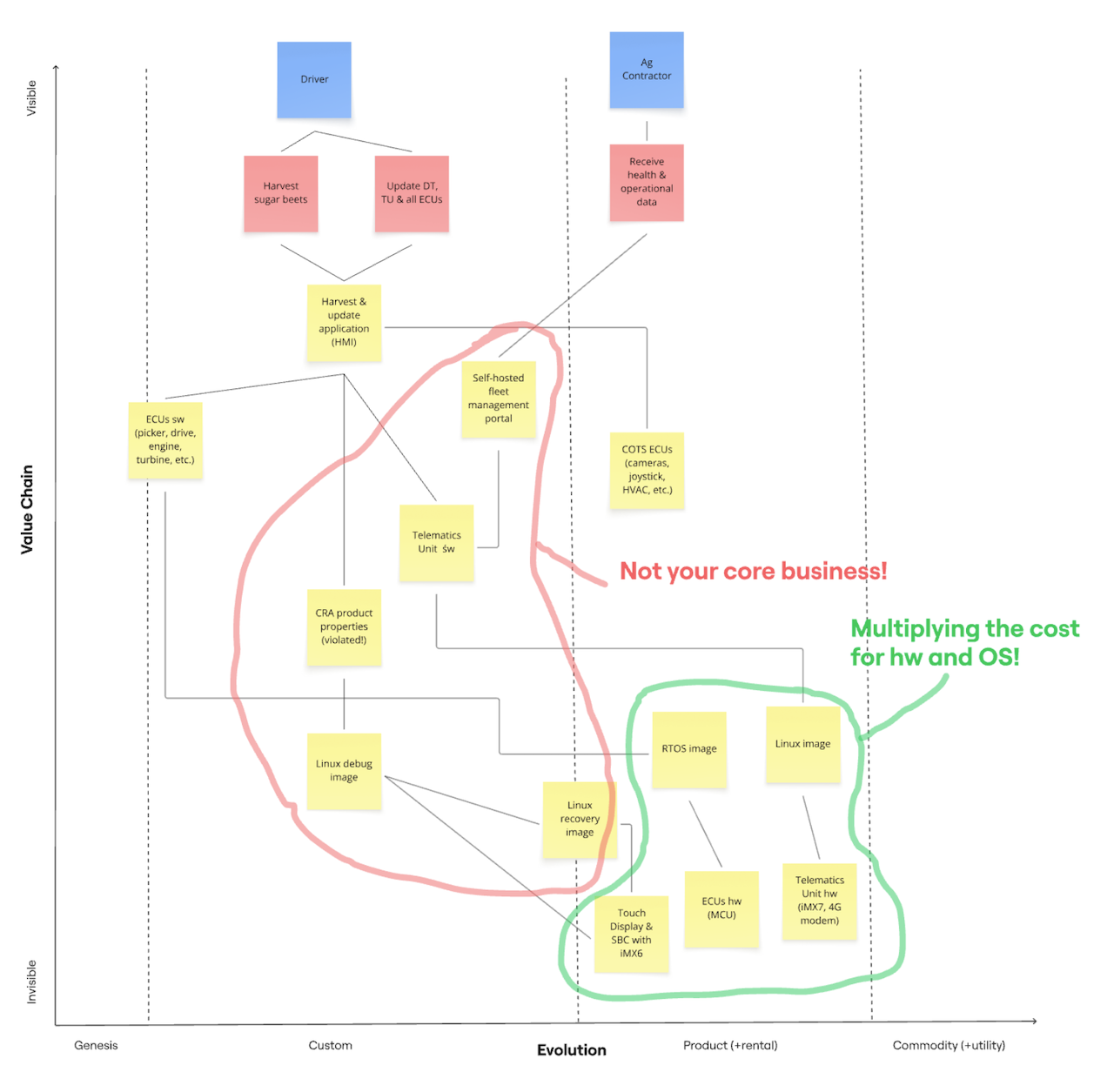
The above Wardley map highlights the business decisions taken during the development of a harvester. We'll find out that many of these big decisions lead to high extra costs during the lifetime of the harvester. The manufacturer could have avoided these extra costs by taking some time early in development and by evaluating the decisions more thoroughly. In short, they should get the big decisions right - early.
On the vertical axis, the Wardley map shows the value chain for the harvester. The users (blue cards) - Drivers and Ag Contractors - are at the top of the value chain. The top priority of the manufacturer is to satisfy the users' needs (red cards). If the Drivers can harvest the sugar beets faster, with less diesel consumption and with less loss of sugar, the farmer, who hired the Driver, makes more money and is happier. The manufacturer created higher value for the farmer.
Drivers get their job done by using the Harvest & update application (HMI) (the top yellow card). They can instruct the harvester to cut the leaves a bit higher to avoid head injuries, to dig a bit deeper to get the beets out of the ground or to clean the beets more thoroughly. Drivers can update the driver terminal (DT), telematics unit (TU) and the ECUs to optimise the harvest or to avoid downtime.
The line between a higher and lower card means that the higher component needs the lower component to get its job done. The user need Harvest sugar beets can only be satisfied by the Harvest & update application (HMI) running on the driver terminal. The Harvest & update application (HMI) sends commands to the ECU s/w (picker, drive, engine, turbine, etc.) and receives operational data from the ECUs to keep the driver informed. The HMI needs the Telematics Unit to send operational data to the ag contractor via the Self-hosted fleet management portal.
The HMI must not violate the CRA properties (the essential product requirements). Unfortunately, it does, as cybersecurity wasn't much of a priority for agricultural machines in the 2010s. The HMI runs on a Linux debug image, which runs on a SBC with iMX6 (single-board computer with an iMX6 SoC). The driver terminal has a Touch Display.
We followed the value chain from the Driver at the top all the way down to the Touch Display & SBC with iMX6 at the bottom. Drivers have no clue that the Harvest & update application (HMI) runs on an SBC with iMX6 - and they shouldn't. This fact should be completely invisible to them. In contrast, the HMI is very visible to the Drivers. Visibility corresponds to value.
On the horizontal axis, the Wardley map shows the evolution stages of the harvester components. The process moving from genesis over custom-built and product (+rental) to commodity (+utility) is called commoditisation.
The stages move from high uncertainty to high certainty. Whereas manufacturers experiment a lot to find a good solution on the left, they can just buy ready-made components on the right. Components on the left are unique and innovative. They differentiate a manufacturer from its competitors. Components on the right are a dime a dozen. Their main differentiator is price.
The manufacturer develops the components in the Genesis and Custom stage itself. In contrast, it buys the components in the Product and Commodity stage or outsources their implementation. High-value components justify the high costs of an in-house development. Low-value components usually don't.
ECU s/w (picker, drive, engine, turbine, etc.), Harvest & update application (HMI) and Self-hosted fleet management portal are high-value components. The manufacturer should definitely develop the first two in-house, because they constitute the competitive advantage for the manufacturer. Collecting the operational data from the harvester fleet is good value, but it doesn't necessitate the umpteenth DIY implementation of an IoT portal.
The remaining four components in the Custom stage are too low-value to justify in-house development. The manufacturer should move these components from the Custom to the Product or Commodity stage. These components are not the core business of the manufacturer. The red outline shows the most likely money pits for the harvester development.
Just because components are in the Product stage doesn't let them off the hook as potential money pits. It's just less obvious. The components in the green outline, the telematics unit and the driver terminal duplicate hardware costs and software development costs. Here are some questions worth pondering.
- What if we merged the driver terminal and the telematics unit into one hardware component?
- What if we combined the 20+ ECUs - including the driver terminal and telematics unit - into 1-3 super ECUs?
- What if we used the same library for processing CAN messages on all ECUs?
- What if we used the same CRA-ready Linux and RTOS images on all ECUs?
- What if we used a commercial OTA update solution?
Focusing on the Core Business
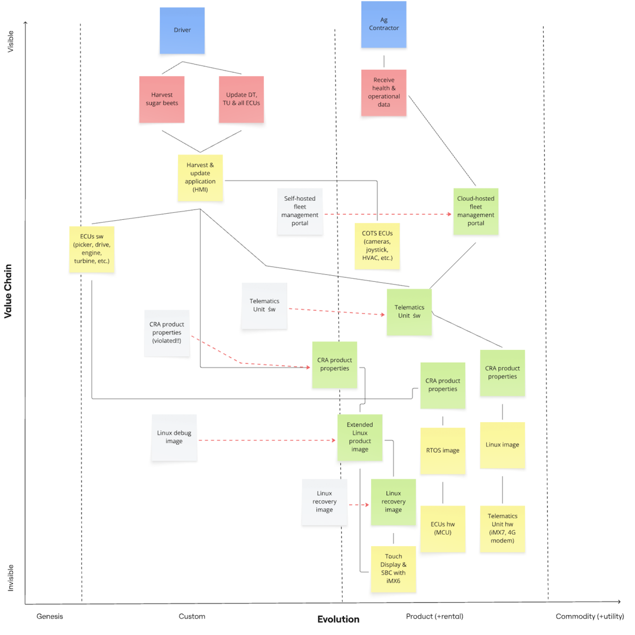
Now that the business people have identified the money pits, it is the job of the system architects to find money-saving alternatives to the in-house development of the non-core business components. They will try to move (red arrow) these low-value components from the Custom (grey box) to the Product or Commodity stage (green box).
The manufacturer hired a service provider to build the fleet management portal from scratch according to its ever-changing specification. It also insisted on self-hosting the portal. It hired another service provider to implement the Telematics Unit s/w that filters the relevant messages from the CAN busses and sends them to the portal. The communication uses a proprietary protocol and happens unencrypted.
Architects could suggest a couple of money-saving alternatives.
- Several end-to-end solutions including a Telematics Unit s/w and a Cloud-hosted fleet management portal exist. Writing a filter for the relevant CAN messages is the only thing the manufacturer must do. Such solutions tend to use proprietary protocols to lock in manufacturers.
- If the manufacturer used a standard IoT protocol like MQTT, it could choose between several free or commercial clients and servers and between self and cloud hosting. The IoT services of the big cloud computing providers support these protocols out of the box. Many smaller providers do the same and offer a dashboard for showing the operational and health data of the device fleet. Of course, these protocols support encryption.
- The manufacturer could use Grafana to build its own dashboard for displaying metrics, traces and logs.
As architects, we could choose a Cloud-hosted fleet management portal that supports a standard IoT protocol and that comes with an easily configurable dashboard for agricultural machines. If such a dashboard is not available, the portal provider could implement the first version and the manufacturer could maintain the dashboard from then on. This reduces the costs for the server side significantly.
The manufacturer of the Telematics Unit h/w most likely has a ready-made CAN-MQTT gateway (the Telematics Unit s/w) communicating smoothly with any MQTT server. We may even find an open-source gateway free of charge. The manufacturer will only have to write a filter for the relevant messages. This reduces the development costs for the manufacturer close to zero.
Using a standard IoT protocol enables us to move the Cloud-host fleet management portal and the Telematics Unit s/w from the Custom to the Product stage. The manufacturer buys these two components instead of developing them in-house and saves a lot of money. This has another big advantage with respect to the CRA.
If the harvester manufacturer develops the CAN-Proprietary gateway itself or hires someone to do so, it must also ensure that the gateway satisfies the CRA product properties. It must perform a CRA compliance for the gateway. Otherwise, the telematics manufacturer is responsible for CRA compliance. That's another good time saving.
The manufacturer of the driver terminal should provide a linux product image that the harvester manufacturer must extend only minimally. This has two advantages.
The harvester manufacturer must only perform CRA compliance for the tiny parts it added to the Extended Linux product image. The terminal manufacturer must do all the rest. This is the first advantage.
The harvester manufacturer saves the time of building and maintaining a custom Linux image for the terminal with features like secure boot, integrity checks for bootloader, Linux kernel and root file system, encryption of sensitive data, secure OTA updates, remote support via VNC or TeamViewer, and more.
The manufacturer will easily spend 6-12 months to create such an image, which it must maintain for the next 15 years. Every OEM buying the driver terminal faces the same costs. It would be much more efficient if the terminal manufacturer provided an image with these features to all OEMs. The manufacturer would only have to add its own applications. This is the second advantage.
The Linux debug image moves from the Custom to the Product stage and is renamed into Extended Linux product image. The Linux recovery image follows suit. It is the last resort if the product image gets corrupted. The terminal manufacturer can provide a ready-made recovery image. That's yet another job less to do for the harvester manufacturer.
If we look at Figure 2 above and ignore the grey boxes, we see that the manufacturer has a laser-sharp focus on its core business. The manufacturer only develops the two high-value components Harvest & update application (HMI) and ECUs s/w (picker, drive, engine, turbine, etc.) in-house. It can even contain the high-value Cloud-hosted fleet management portal from external sources. The manufacturer buys the lower-value components from third-party vendors and gets away with very little integration, configuration and compliance work.
Less Hardware, More Software
So far, we have saved money by replacing in-house development by buying, leasing or subscribing to ready-made products. These products might need a bit of straightforward configuring or customising but no serious development. Moving components to the right in the Wardley map, that is, commoditising their development, frees resources for the core business.
We cannot only save money by moving boxes to the right but also by making boxes disappear. I am not only talking about the boxes in the Wardley map but also about the hardware boxes in the harvester. Merging two or more hardware boxes into one and turning hardware into software has good money saving potential. This answers the what-if questions at the end of the section Identifying the Money Pits.
Merging Driver Terminal and Telematics Unit
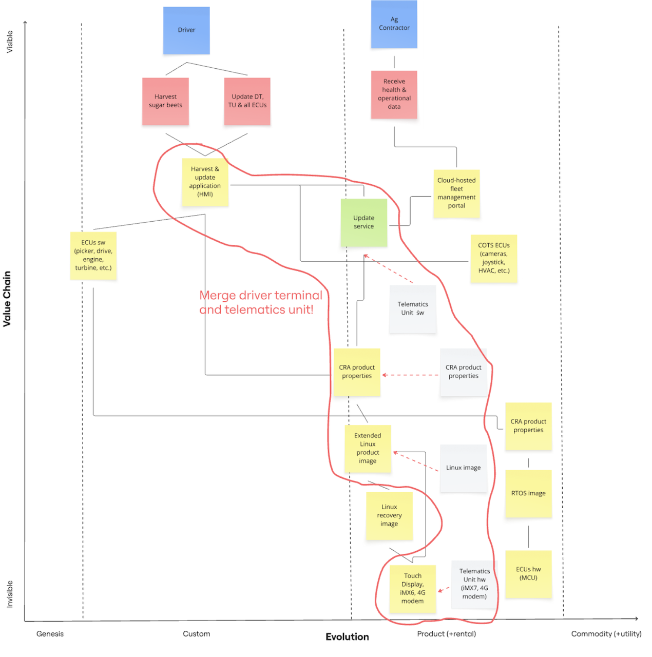
The driver terminal costs roughly €1,400 and the telematics unit €500. If the manufacturer could buy the 2-in-1 unit for €1,650 instead of €1,900, it would save €125,000 for 500 harvesters per year. That's a substantial saving and pretty realistic.
Merging the Telematics Unit h/w into the Touch Display amounts to putting a 5G modem into the Touch Display. The manufacturer shouldn't have problems to find a supplier offering a terminal variant with a modem or willing to fit the modem into the terminal.
The merging moves from hardware to software. The terminal manufacturer integrates the modem-specific Linux functionality - the Linux image of the telematics unit - into the Extended Linux product image of the driver terminal. Similarly, it performs the CRA compliance of the modem - satisfying the CRA product properties - as part of the compliance of the whole driver terminal. Note that the driver terminal stays a default product, although it includes an important class-I product with the 5G modem (see Article 7.2 and my explanation Critical, Important and Default Products).
The manufacturer of the telematics unit is very likely to have a CAN-MQTT gateway - the Telematics Unit s/w - on offer. This is less likely for the manufacturer of the driver terminal. However, terminal manufacturers could regard such a gateway as a competitive advantage and provide it. They actually do a very similar thing with implementing ISOBUS applications for agricultural machines.
If the terminal comes without a gateway, the harvester manufacturer can reuse the CAN message processing module that is already available for the Harvest application (HMI). The gateway filters out the few relevant CAN messages, converts them into MQTT messages and sends them to the fleet management portal. The manufacturer might find a free or commercial gateway instead of developing it in-house. Anyway, it must include the gateway in its CRA compliance. Integrating a gateway is a small one-time cost.
Now that the driver terminal has an Internet connection via the 5G modem, it is time to abandon the home-grown and error-prone update solution for a few ECUs in favour of a professional OTA update solution for all ECUs. These solutions come as an Update service running in its own process. The Harvest application (HMI) receives notifications from and sends commands to the Update Service via inter-process communication like DBus and gRPC.
The Update Service checks the availability of updates with the Cloud-hosted fleet management portal and downloads updates from the portal. It orchestrates the update of the driver terminal and all ECUs.
Merging Many ECUs into Few Super-ECUs
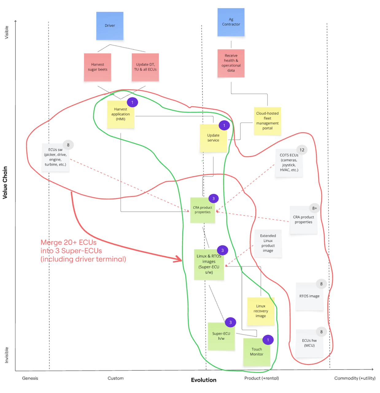
So far, the Wardley maps have been hiding the fact that the manufacturer has customised 8 ECUs (picker, drive, engine, turbine, etc.) and integrated another 12 COTS ECUs (cameras, joystick, HVAC, etc.). This is the traditional flat architecture, where every function gets its own hardware box and the boxes are wired up with kilometres of cables.
We can use the same idea as for the driver terminal and telematics unit and merge the 20 ECUs (red outline in Figure 4) into 3 more powerful ECUs or super-ECUs (green outline in Figure 4). The result is a zonal architecture (PDF) as it has become common for electric vehicles. The hardware functions are turned into software functions.
The zones for a harvester suggest themselves: the front zone for the front implement, the middle zone for the driver and the rear zone for engine, drive, turbine and conveyor belts. The zone controllers or super-ECUs are connected directly to sensors and actuators via GPIOs. They are connected to each other via Ethernet.
Let us first understand how the 8 ECUs (picker, drive, engine, turbine, etc.) are merged into the front and rear super-ECUs. The eight "old" ECUs run an RTOS, which is developed by the ECU manufacturer, on a microcontroller. The harvester manufacturer adds some code to control mechanical parts like cutting knives, cleaning turbines, conveyor belts, drive and engine. The harvester manufacturer must perform CRA compliance for this code, whereas the ECU manufacturer must do it for the RTOS and hardware.
When the harvester manufacturer moves the functions of the old ECUs to the front and rear super-ECU, it has several options.
- The ECU manufacturer has more powerful ECUs on offer with the same RTOS. A custom RTOS means lock-in for the buyers and higher prices. It typically has more bugs, because less people use and test it than a standard RTOS. This option is unlikely, because the manufacturer would cannibalise its own business.
- The harvester manufacturer buys the super-ECU with a custom RTOS from another vendor. The vendor lock-in and the higher likelihood of bugs remains.
- The harvester manufacturer buys the super-ECU with Zephyr. Zephyr has become the de-facto standard for RTOSs over the last years. It is free and open-source, has plenty of community and commercial support and runs on nearly every hardware platform. As Zephyr is developed, used and tested by thousands of people daily, its quality is much higher than for custom RTOSs.
The best option is the super-ECU with Zephyr. Free open-source software like Zephyr and Linux is clearly a commodity. Commodities increase the flexibility to change the vendor of the super-ECU easily. They also reduce the costs. Just an example: Eight boxes for €800 are a lot cheaper than two boxes for €1,500. And don't forget to multiply the difference by 500 harvesters per year.
As commodities, Zephyr and Linux should be on the far right of Wardley maps. But this would be hard to draw, because the harvesting-specific code would pull it back into the Custom stage. Hence, they ended up in the Product stage as a compromise.
Merging the 12 COTS ECUs (cameras, joystick, HVAC, etc.) into the middle super-ECU - the driver terminal with the software telematics units - needs a bit more thinking. These ECUs have different functionality and come from different manufacturers.
The joystick, rotary knobs and buttons are located on or near the armrest and the driver terminal (see the cabin of the ROPA Tiger 6S). They are ECUs and send their actions via CAN bus to other ECUs. They don't receive any CAN messages. With the zonal architecture, the driver terminal is linked to the joystick, rotary knobs and buttons in a point-to-multipoint RS485 connection. The driver terminal acts as a gateway and forwards the relevant messages to the front and rear super-ECUs. HVAC works the same, although the communication is bidirectional. RS485 wiring is cheaper than CAN wiring.
Manufacturers have three general options to integrate radios.
- The radio is a standalone device not integrated in the on-board network. The driver must operate the radio directly. Streaming music from the phone via Bluetooth is only possible, if the radio supports it. The radio is not merged into the driver terminal.
- The radio and the driver terminal are connected through CAN bus, which is replaced by an RS485 cable. The driver controls the radio (e.g., switch the station, increase the volume) through the HMI of the terminal. Again, streaming music is only possible, if the radio itself supports it. This setup is convenient for the driver, if the radio is installed above the windscreen and hard to reach for the driver.
- The manufacturer could integrate the radio antennas into the driver terminal and connect the loud speakers to it. The driver can stream music from his phone via Bluetooth. This is the standard setup for cars. Merging the radio into the terminal is similar to merging the telematics unit into the terminal.
Smaller manufacturers typically use the first or second option because of the low integration effort. Bigger manufacturers go for the third option, because drivers expect the same user experience as in their cars. The integration effort is high compared to the other two options. The manufacturer must weigh the integration costs against the cost savings of getting rid of the radio box. The second option may be a good and economical compromise.
The 360-degree surround view system consists of four cameras connected via Ethernet to an ECU for image processing. The ECU acts as a switch with for incoming Ethernet connection from the cameras and one outgoing Ethernet connection to middle or rear super-ECU. It also mixes the four videos into one surround view video and it can detect obstacles. The driver terminal receives the surround video and displays it. We could leave the setup like this and accept the surround view system as an extra ECU in the local area network.
Alternatively, we could replace the surround view ECU by a dumb switch and move the video mixing and the obstacle detection software to the driver terminal. The dumb switch needs at least 5 inputs to accommodate for the separate turbine camera. How the one-time and recurring costs of the old and new solution compare is an open question. If the manufacturers plans to add more cameras for automated harvesting in the future, the dumb switch solution will get more interesting. This might, however, require a more powerful SoC for the middle super-ECU.
References
- Simon Wardley, Wardley Maps - Topographical Intelligence in Business. This free online book is the ultimate reference about Wardley maps by the creator himself. Chapter 2 - Finding a path explains in detail how to map a business strategy. Improving the strategy is the topic of the following chapters.
- Susanne Kaiser, Architecture for Flow: Adaptive Systems with Domain-Driven Design, Wardley Mapping, and Team Topologies. Addison-Wesley Professional, 2025. Chapter 1 - Business Strategy with Wardley Mapping is a very instructive introduction into Wardley mapping for software products. It gave me the information and motivation to write this post.
- Ben Mosior, Understand context and diminish risk: How build your first Wardley map. Ben describes how to use the Miro to create Wardley maps. I created all Wardley maps in this post with Miro.